 Return to Basic Equipment Menu |
|
 Return to Basic Equipment Menu |
|

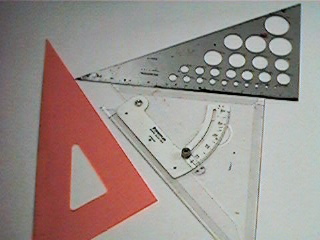
These tools can also come in quite handy when trying to keep hatching angles consistent. The simplest way to use one is to run it along a given straight edge such as a t-square, ruler or the edge of a sheet of paper.
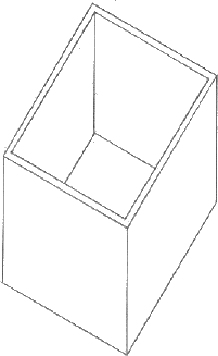
Because it lacks some expected depth clues, an architectural perspective might appear skewed to our eyes. A drawing like this would be most useful when showing someone how to build an object to scale. Each edge can be measured accurately in proportion to all other edges. The 90 degree angles of top and bottom are also maintained, while the front and sides are bent to 60 and 30 degrees respectively from the vertical axis.
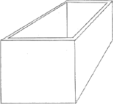
This drawing contains many expected visual depth clues. As dictated by the rules of linear perspective, parallel lines converge to a single point. With only one vanishing point, the front remains squared, leaving the front left corner looking a little warped. Measurements could theoretically be taken from the front end of the box to be interpolated to the rest of the form by logical inference. Still, as a building plan this picture would require quite a lot of unwanted interpretation on the part of the carpenter.
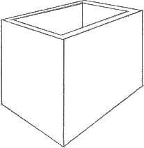
Image warping is minimal in this rendering, and visual depth clues abound. All receding lines converge to vanishing points, and actual plan measurement would be extremely difficult. Vertical lines are still consistently parallel, allowing for the possibility of scaling using logical inference, but the prospect of determining actual measurements would prove unappealing to most.
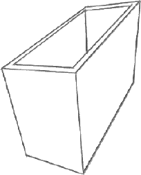
All linear perspective depth clues are in place, and the object appears visually correct. All parallel lines converge to some point in space, leaving actual measured proportions obscure at best. This sort of rendering might sell a product or look more realistic, but as an architectural plan goes, it is almost useless.